
What you will need:
Although there have been many advancements in the NES RGB modding scene, this particular mod has a few advantages over the newer ones. Space savings being the major one, as well as ease of install. The drawback to this old school method is that you NES will essentially be "supergunned" and you will lose your composite output.
Additionally, most NES games were made with composite output in mind, so when paired with a PC-10 PPU you will sometimes get some odd colors, such as pinks where maroon colors should be. Personally, I actually prefer the PC10 colors and think they look kind of neat.
There are also a small handful of games that will not function with this mod, mostly those that use color emphasis bits. These titles will give a white screen at startup, making the game unplayable. There are only a handful of games that use these bits, and most of them are games you probably would not want to play anyway, with the notable exception being Just Breed. This is an amazing SRPG for the Famicom that has been fully fan translated.
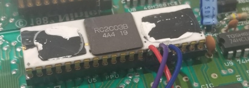
If all that doesn't bother you, you will want to look for a VS or Playchoice-10 PPU. These were special PPUs made specifically for Nintendo's stand up arcade cabinets. The most common one being models Rx2C03x (the other letters in the model code don't matter) as these PPUs actually output a much improved RGB signal in place of the composite video found on the stock chips used in most NES consoles.
Removing The PPU
In order to desolder the PPU you will need a desoldering gun, desoldering wick, or pump. For this mod I highly recommend you avoid the manual methods and just get yourself a desoldering gun since desoldering the PPU without a gun is extremely time consuming. Besides, a desoldering gun will serve you well in the long run especially if you do other mods on your consoles.

There's no doubt about it - desoldering the PPU is the most difficult part of the mod. If you've never done this before or do not have a whole lot of experience with desoldering components, save yourself the headaches and get a used Hakko 808 or 301.
To start, you will want to add some fresh solder/flux to the pins on the PPU. This will make it easier to desolder them. Most of the pins will be relatively easy to free however special care should be taken with pins in the top right as they are attached to the ground plane in the PCB and can suck up a lot of heat. Don’t be afraid to add more solder to these if you can't fully free them on the first go around.

Before you add the PC10 PPU to your socket, you will want to clip pins 14, 15, & 16. These are the RGB pins. On a normal NES PPU they are grounded and have no function. This will cause problems with our mod so we will have to isolate them out of circuit to ensure proper function. You can also pull the pins out and shorten them but I find cutting them is easier.

If you want to be extra safe, a piece of tape over the VIAs doesn’t hurt.

You should also add a 60-120uf cap between the OE/WR line. This is due to the fact that the NES isn't designed to be used with an RGB PPU, so there will be a few graphical glitches in certain games. Adding in this capacitor here should clear most of those up.
Adding The Output
Unfortunately for us the RGB from this PPU is not amplified which means hooking up your monitor to this console will result in a very dark picture. To get around this you can build your own amp or use the popular THS7314/7316. To keep things simple, i prefer to use the standard THS amps as they work with the majority of Nintendo consoles. You can also buy a SOIC adapter that the amp can sit on top of, so you don’t have to solder to its tiny legs. Add a 0.1uf cap between 5v and ground, and 3 75ohm resistors on the outputs. This will dampen the output and make it more in line with a proper RGB signal.

Now that the hard part is over with its time to connect our video & sound output. : R, G, B, come from pins 14, 15, & 16 on the PPU.

Composite sync, mono audio, & audio ground can be pulled from the RF box after you take the metal cover off, assuming you have a front loader.

5v, & video grounds can be had from these 2 points near 72 pin connector.

Since the NES doesn’t have anything other than a composite connector, you will have to add your own output. A popular choice is an 8 or 9 Pin mini din, a connector that is commonly found on Genesis/Megadrive consoles. This enables you to use a Genesis SCART cable interchangeably. I like to stick with Nintendo style connectors, and will generally use a Multiout as it looks a lot better and is easier to work with. Many places sell Multiout connectors that have their own PCB, which makes soldering a much easier task. You can also use one from a dead SNES/GC console as well.
Add your RGB, power/ground, and audio to your preferred connector and mount the amp in a good place. In this case I opted to mount it on back of the Multiout, as i want to save a much space as possible for future mods.

You will probably have to do some drilling if you have a top loader like I do. If you’re going with a multi out connector, here is a template for a Multiout i used, with exact measurements.

It’s best to drill a smaller hole with a dermal and file the rest out manually. Beware that the plastic on an old NES is quite brittle, as most of these consoles are over 30 years old at this point. Go as slowly as possible, using the lowest speed on the Dremel.
The NES Playchoice-10 chip uses what’s known on Tims NESRGB kit as the "garish" pallet, which I personally think looks very retro and I much prefer it to the other generic looking pallets on his kit. As far as nes rgb mods go, this one is a breeze to install when compared to more popular solutions.